Zirconia Oxygen Sensors from SST can be at times difficult to understand how they operate. We have screeds of documentation that explains the background physics and the oxygen sensor function but you need all the time in the world to be able to sit down and read these pieces to know and understand what they mean.
This article simply takes all of that information and structures it in a way that is easy to read and understand.
Oxygen Sensor Function
Sensor Cell Construction
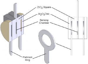
At the core of SST’s zirconia oxygen sensors is the sensing cell (Figure 1). The cell consists of two zirconium dioxide (ZrO2) square coated with a thin porous layer of platinum which serve as electrodes provide the necessary catalytic effect for the oxygen to dissociate, allowing the oxygen ions to be transported in and out of the ZrO2.

The two ZrO2 squares are separated by a platinum ring which forms a hermetically sealed sensing chamber. At the outer surfaces, there are two further platinum rings which along with centre platinum ring provide the electrical connections to the cell.
Two outer alumina (Al2O3) discs filter and prevent any ambient particulate matter from entering the sensor and also remove any unburnt gases. This prevents contamination of the cell which may lead to unstable measurement readings. Figure 2 shows a cross-section of the sensing cell with all the major components highlighted.
The cell assembly is surrounded by a heater coil which produces the necessary 700°C required for operation. The cell and heater are then housed within a porous stainless steel cap to filter larger particles and dust and also to protect the sensor from mechanical damage. Figure 3 shows the complete sensor assembly.

Pumping Plate
The first ZrO2 square works as an electrochemical oxygen pump, evacuating or re-pressurising the hermetically sealed chamber. Depending on the direction of the DC constant current source, the oxygen ions move through the plate from one electrode to the other, this in turn changes the oxygen concentration and therefore the oxygen pressure (P2) inside the chamber. The pumping is controlled so that the pressure inside the chamber is always less than the ambient oxygen pressure outside the chamber. Figure 4 shows the electrical connections to the cell.

Sensing Plate
A difference in oxygen pressure across the second ZrO2 square generates a Nernst voltage which is logarithmically proportional to the ratio of the oxygen ion concentrations. As the oxygen pressure inside the chamber (P₁), the voltage at sense with respect to common is always positive.
This voltage is measured and compared with two reference voltages and every time either of these two references are reached, the direction of the constant current source is reversed. When the ppO2 is high, it takes longer to reach the pump reversal voltages than it does in a low ppO2 atmosphere. This is because a greater number of oxygen ions are required to be pumped in order to create the same ratiometric pressure difference across the sensing disc.
Example
P1, the O2 pressure we want to measure, is 10mbar and the set reference voltage is achieved when P2 is 5mbar. If P1 is then changed to 1bar, P2 would have to be 0.5bar in order to achieve the same reference voltage. This would involve evacuating far more oxygen ions and as the current source used to pump the ions is constant, would therefore take a lot longer.